Batteries
The project has two batteries, the Turnigy and "Battery A". Turnigy is a battery purchased with LI-PO (lithium polymer) technology with a minimum capacity of 10000mAh and a maximum voltage of 14.8V in the 4S1P configuration. Battery A" is an assembled battery whose information was provided by Salviano, and has an average voltage of 12V (with a maximum voltage of 16.8V) and a capacity of 12500mAh in a 4S5P configuration.
The information obtained from both batteries has been compiled in the table below:
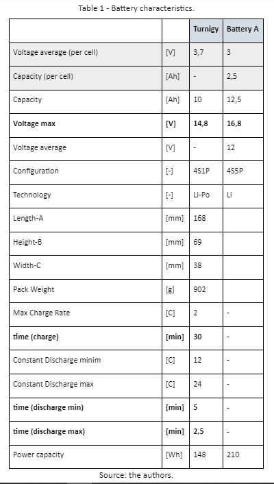
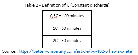
How the Turnigy information was obtained from the datasheet provided on HobbyKing's website. We were able to get more detailed information such as the loading and unloading time according to the manufacturer. Just remembering that: HobbyKing. Conseguimos obter informações mais detalhadas como o tempo de carga e descarga de acordo com o fabricante. Apenas recordando que:
Finally, “power capacity” refers to the amount of energy stored in the battery, this value is obtained by multiplying the current [A] and voltage [V].
With the information from the two batteries and considering the scenario that these batteries actually have and reach the values obtained in table 1, a configuration was created that would enhance the capacity supplied to the system, in this case using them in parallel (10A + 12, 5A = 22.5A). Reinforcing that we are assuming that the batteries are in good condition, so the required discharge time (not considering any percentage of discharge safety, which would be a percentage of the capacity that will never be used, usually 20%) is obtained t = (capacity [ Ah] / current [A])*60, to get the answer in minutes.
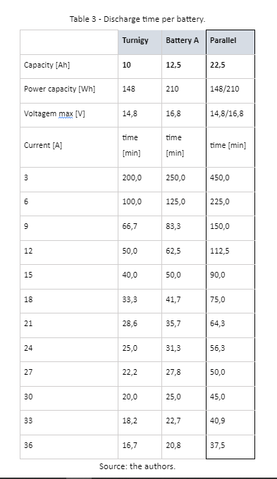
Just for better visualization purposes, the graph with the data is shown below.
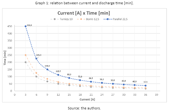
As can be expected, the battery mounted in parallel is discharged faster as the current increases. The challenge then is to find a current that meets the system and that is long enough to complete the race path, considering possible unforeseen events. In addition, there is a serious aggravating factor regarding the temperature increase, which can contribute to the overheating of the AUV. As we have no data from the manufacturer regarding temperature tests in relation to the discharge current, an alternative would be to perform our own test in the laboratory.
According to the survey done for the last edition, the components that demand energy from the system were:
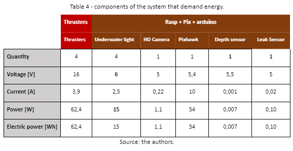
The values for the number of components required in the AUV, voltage, current, and power were taken from the datasheets available on the Blue Robotics website (https://bluerobotics.com/) and these values are also available in the tab "System_Demand". Blue Robotics e estes valores também estão disponíveis na aba “Demanda_sistema”.
With the data compiled, we noticed that there is a voltage range (6V-16V) between the components that can hinder the operation of the system, besides the alternative of inserting all components in the same enclosure and inserting a device that does not affect the components that need low voltage, an alternative of a second enclosure was proposed.

The data obtained refer to the amount of current and power that the system will demand for operation, so it is a parameter for the battery to ensure the supply for the entire system.
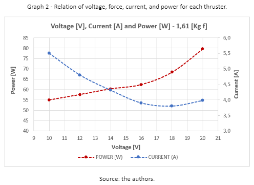
The information on current, power, RPM, and efficiency according to voltage can be found in the excel file "T200-Public-Performance-Data-10-20V-September-2019" in the attachments, but the compilation of the information is below.
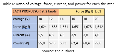
We were able to observe that there is an interesting trade-off for our goal, in which the thruster is able to provide a higher power with a lower current. trade-off interessante para nosso objetivo, no qual o propulsor consegue fornecer uma maior potência com uma corrente menor.
Considering the scenario that all components are in only one pod, and that the voltage, current, and power values required by the system are as discussed above with the components listed above, we get the following data:
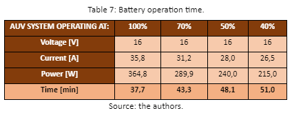
The information of the percentage of system operation at 100%, for example, considers that the components will be operating at their maximum capacity at all times of operation.
Thus, we can estimate the battery operating time to meet the system's needs considering some scenarios of component operation.